Recreational
boats operating at night are required to display navigation lights
between sunset and sunrise.
Basic rules:
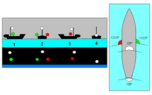
Sidelights are red (port) and green (starboard) and shine from dead ahead to 112.5° aft on either side.
Stern
lights are white and shine aft and 67.5° forward on each side. (Thus,
the sidelights and stern light create a full circle of light.)
All-round lights are white and shine through 360°.
Masthead
lights are white and shine from 112.5° on the port side through dead
ahead to 112.5° on the starboard side. They must be above the
sidelights.
Sailboats under power are considered powerboats.
Sidelights may be combined into a single "bicolor" light.
Powerboats
less than 20m (65.7') in length need to show sidelights, a stern light
and a masthead light. Power vessels less than 12m may show a single
all-round light in lieu of the separate masthead and stern lights.
Sailing
vessels less than 20m in length need to show sidelights and a stern
light. These may be combined into a bicolor light and stern light, or a
single tricolor light at the top of the mast. Sailing vessels under 7m
must have an electric torch or lantern available for collision
avoidance.
Oar-driven vessels can show either the sailboat lights, or use the electric torch/lantern option.
When
anchored outside a special anchorage, power and sail vessels under 20m
must display an all-round light. Vessels under 7m are exempt, unless
anchored in a narrow channel or anchorage, or where other vessels
usually navigate.
Sailboats with sails up during the day, but
which are also under power, must fly a black "steaming cone," with its
point downward, where it can be seen. When under power they must follow
the rules of the road for powerboats.
Notes
Boats under power under 40' can substitute a single all-round light for separate stern and masthead lights
Boats under 65'7" can substitute a single bi-color light for sidelights
Sail boats under sail under 65'7" can substitute a tri-color light for separate sidelights and stern light.
All-Round Light: White (32pt/ 360°) Masthead Light: White (20pt/ 225°) Sidelights: Red (10pt/ 112.5°) & Green (10pt/ 112.5°) Stern Light: White (12pt/ 135°)
Boat Light Template
Navigation Light Switching for Vessels Under 20 Meters
The possible switch configurations for navigation lights vary greatly
depending on the vessel size, type, and purpose. This article addresses
the most common configurations for smaller vessels.
ABYC
standards state that one switch, or position of a switch, will turn on
all of the navigation lights required for the vessel while underway.
Another switch, or position of a switch, will turn on the anchor light.
This allows the use of either 2 switches or a 3 position switch with one
off position.
The most common configurations of lights are:
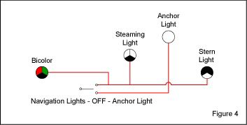
A bicolor light with an all-round (360°) white light
A bicolor light with a 135° stern light and a 225° masthead light and a 360° anchor light
Two sidelights with an all-round (360°) white light
Two sidelights with a 135° stern light and a 225° masthead light and a 360° anchor light
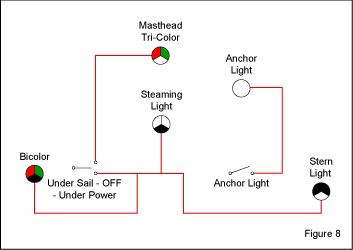
A masthead tri-color light with a 225° masthead light and a 360° anchor light
these can be broken down into 3 combinations:
A bicolor or two sidelights and an all-round white light
A bicolor or two sidelights with a 135° stern light and a 225° masthead light and a 360° anchor light
A masthead tri-color light, a bicolor or two sidelights, a 135° stern light, a 225° masthead light, and a 360° anchor light
The
following illustrations use a bicolor, but two sidelights can be
substituted for it in the diagram. All of the double throw switches are
"Center Off".
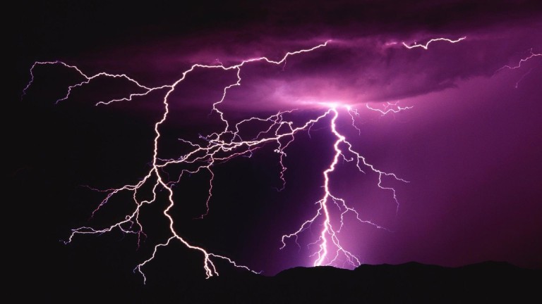
When lightning strikes, and it does, having a lightning protection system can save your life
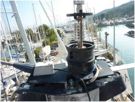
We were lucky when we were struck by lightning on our small 35’ GRP
cruising sailing boat in Turkey in 2013, but without an LPS. All the
plastic and some of the metal gear at the top of the mast exploded (see
photo below) and simultaneously the headlining in the saloon exploded
downwards with a loud bang. So much smoke that we initially thought we
were on fire; but my wife and I survived unscathed to tell the tale.
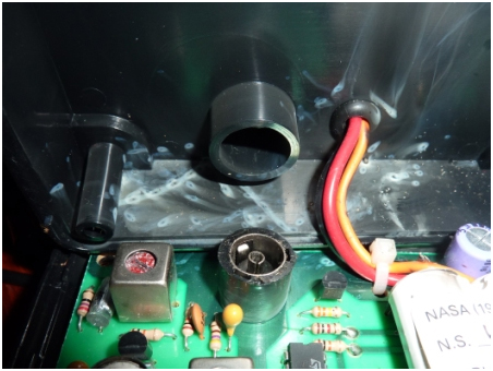
The most likely discharge exit was through the propeller shaft, but
practically all electronics were violently destroyed and, as an
electrical and electronic engineer, my assessment for our insurance
claim afterwards showed that most devices had experienced severe arcing
with small electronic components having exploded internally (see photo
below).
An lightning protection system is a
bonding, grounding and shielding arrangement made of four distinct
parts: Air terminals, down conductors, a low-impedance ground system and
sideflash protection.
The best lightning protection system cannot guarantee personal
protection, or protection from damage to sensitive electronic equipment.
Also it is not a lightning prevention system. I knew the private owner
of one large blue water catamaran which has been struck three times in
its life and it is not an old boat. Fortunately no one was hurt on any
occasion, but many electronic systems on that complex boat were effected
and had to be replaced on each occasion. Unfortunately catamarans are
many times more likely to be struck than mono-hulls and records in the
USA, where certain locations are particularly prone to electrical storms
(e.g. Florida where boat ownership is high), show that mono-hull
sailing boats are about 25 times more likely to be struck than
motoryachts.
Lightning is very hard to study and to accurately predict its
behaviour is almost impossible, but it is driven by the simple fact that
a massive potential difference (voltage) exists between the highly
charged clouds of a brewing thunderstorm and the surface of the Mother
Earth. Eventually, a path is found through the atmosphere down to ground
for some of the accumulated charge to discharge and the creation of a
discharge path first requires the creation of so called ‘streamers’
[1],[2]. Bear in mind that air breaks down at 3 million Volts per metre,
and you get some inkling of the enormous voltage differences involved.
In the middle of a large body of water, with your sailing yacht in
it, the top of the mast, being the highest point around, looks like a
handy point to discharge through. So the LPS is designed to control the
first point of discharge and then make the onward path to ‘ground’ – in
this case the sea – as direct as possible and capable of conducting very
high currents for a very short time during the discharge.
In 2006, the American Boat and Yacht Council (ABYC) technical information report TE-4 [3], [4] recommended the following:-
• lightning protection system conductors must be straight and direct
and capable of handling high currents. The main ‘down’ conductor is
recommended to be 4AWG, or 25mm2 in European sizing; see diagram.
• A large enough area ground must be provided between the vessel and
the water to offer an adequately low resistance path (ABYC recommends
1sq.ft. {0.1m2} in salt water; much larger in fresh water. NB this is
not adequate for acting as the SSB counterpoise). Metal-hulled vessels
naturally offer a large ground contact area with the sea, but the
connection between the hull and all other electrical systems needs
careful consideration.
• Heavy metal objects such as fuel tanks and engines must be bonded
to the ground bonding arrangement to reduce the risk of ‘side flashing’
where the lightning literally can jump from one conductor to another,
seemingly better path. Similarly, it can jump out of corners in cabling,
so if bends must be made, then they should not be more than 90° and
with as large a bend radius as possible.
The basic arrangement is as depicted in the diagram, where the ‘air
terminal’ is a rounded end (circled in photo) metal wand mounted at the
top of the mast to ‘attract’ lightning to it and, most importantly, to
stand at least 6” (15cm) higher than anything else e.g. above the VHF or
other antenna. Providing the air terminal is securely electrically
bonded, presenting a high surface contact area, low resistance path to
an aluminium mast, the mast itself can be used as the down conductor at
least to the deck or keel, depending on where the mast is stepped. In
the case of wooden, or carbon composite masts they present too high
electrical resistance and a 4AWG cable must be run straight down the
mast as the main down conductor. From the bottom of the aluminium mast
or down conductor, the 4AWG onward path needs to be as direct and short
as possible to the ground plate, or the metal hull.
The
size of the ground plate as the main electrical discharge route out of
the vessel is important and there is evidence that the shape is
important as well: A long, 1ft2 {0.1m2} area copper strip, in contact
with the water is believed to be more effective than a square of copper
of 1ft2 as it is believed lightning will exit from the edges rather than
the face of the ground plate.
It is actually better to leave through-hull metal fittings
electrically isolated if they are already insulated from the rest of the
boat by dint of their attached rubber or plastic hoses and their
insulating mounting plates – decent quality bronze alloy seacocks and
engine intake strainers will not unduly corrode if left submerged for
extended periods of time without needing connecting to the vessel’s
earth bonding. However, in the US it is more normal to bond everything
metal below the waterline, use a tinned copper bus bar running the
necessary length of the vessel, above any bilge water level, to connect
each through-hull fitting to, which is then connected at one point only
to the main grounding route out of the boat. This bonding arrangement is
gaining in popularity outside the US with consideration of a lightning
protection system.
Note in the diagram that all tie-ins, including fore- and back-stay
(unless insulated) must use at least 6AWG (16mm2 European) cable. All
large metal objects within 6ft (2m) of the lightning down path also need
tying in with 6AWG (16mm2) cable. Examples are metal fuel tanks, main
engines (despite them usually already being connected to the water via
their prop shaft) and generators; this is to minimize the risk of ‘side
flashing’ where lighting can literally jump from conductor to metal
object, looking for a better path to ground, even if one does not exist.
In considering of the creation of a ground plate of sufficient size, a
metal hulled vessel is ideal, but nevertheless only one electrical
connection point to the hull should be made from the main 4AWG down
conductor. This same point should have all the other earth bonding made
to it alone. The DC main negative bus in turn should be connected to the
earth bonding in only one place, though European boats generally have
their DC system isolated from any bonding system to discourage DC earth
faults, the US differs in this respect, preferring direct bonding. One
solution to this dilemma is to use a suitably rated surge capacitor
between the DC negative busbars and the bonding system for the LPS. In
the case of a non-metal hulled sailing vessel, the attraction of using
the keel as a discharge point should be resisted as it is in contact
with the water some distance below the surface where already a lot is
going on with respect to charge balancing, so an alternative point is
likely to be sought out by the discharge, nearer the surface. It seemed
clear to our very experienced (and ancient) marine insurance surveyor
that, during our own strike in Turkey, the discharge was out through the
propeller shaft.
So far, so good, but recent thinking and good practice [5],[6] has
modified the above ideas to take into consideration the danger of side
flashing much more. A side flash is an uncontrolled spark that carries
current to the water and can do extensive damage to hulls and equipment.
The good practice and standards for a lightning protection system
relating to marine situations, such as they exist (see NFPA 780, latest
version, especially chapter 8, ‘Protection for Watercraft’, [7]) are
tending to treat a boat more and more like a building to exploit those
well tried and tested techniques used in a land based situation. Rather
than a ‘cone’ below the air terminal, the ‘zone of protection’ is now
more reliably envisaged to be formed from a ‘rolling sphere’ of 30m
radius, as shown below for a larger yacht [7],[8]:-
Diagram of Boat with Masts in Excess of 15 m (50 ft) Above the Water;
Protection Based on Lightning Strike Distance of 30 m (100 ft).
With a large building, the down conductors from the various air
terminals run down the outside of the building to a number of grounding
stakes; not so with a yacht where, as we have described, we’ve now
concentrated the discharge right in the middle of the boat, where the
danger of side flashing into other metal parts is very real; if these
parts are not bonded and protected by a properly designed, low impedance
path there’s are very real further danger of the side flash finding its
way onwards and out through the side of the boat to the surrounding
water surface. This has indeed been experienced by an American friend of
mine on a high-tech, all carbon racing sailing boat on its way back to
Newport, which after being unavoidably struck several times in a violent
storm, put in to New York and immediately hauled to find literally a
thousand or more tiny holes around the waterline when the discharge had
exited! Apparently lightning does not always take the straightest path
to the water, but rather has an affinity for the waterline.
The latest version of this NFPA 780 standard recognises this danger
and, in a departure from the older versions, provides for multiple
grounding terminals to provide the shortest path to the surrounding
water surface. These ‘supplemental grounding electrodes’ conduct
lightning current into the water in addition to that conducted by a main
ground plate. The new standard provides for a continuous conducting
loop outboard of crewed areas, wiring and electronics. Placing the loop
conductor well above the waterline, outboard, and with grounding
terminals below it retains the advantages of an equalization bus, whilst
correcting for its weakness with side flashes having nowhere else
otherwise to go. Finally
– what does an lightning protection system do to protect sensitive
electronic equipment? The simple answer is very little. The huge
potential difference between sky and Mother Earth in a thunderstorm can
cause an electrical discharge of immense energy, with huge current
flows, but only lasting fractions of a second. If that current is
running down your aluminium mast and safely out of the ground plate and
supplemental grounding electrodes of your boat through the Lightning
Protection Scheme measures you have taken, without blowing a seacock off
the bottom, without starting a fire and without injury to anyone one
board, that is the primary consideration and what the system is most
hoped to achieve. However, in the controlled (as much as possible)
passage of that enormous current, your electrical cables connected to
sensitive electronic equipment should be as separated as possible from
the discharge route, and if you can ensure those cable runs are at right
angles to the discharge path direction to minimise large induced
currents, then you are beginning to understand the correct philosophy.
Some additional measures are offered on the market – for instance surge
arrestors, and special in-line VHF aerial suppressors – but the best
insurance of all is to completely isolate the most sensitive electronic
devices when a thunderstorm is brewing i.e. turn off and completely
disconnect such devices from any installed piece of wire or cable on the
vessel.
Protection of electronic equipment by a hermetic system on larger yachts
So much electronic equipment on board a yacht struck by lightning is
very susceptible to permanent damage. The only safe way to fully protect
electronic equipment is to have it completely disconnected from all
other circuits when thunder and lightning are nearby, and I still to
this day do that as much as possible, but how practical is complete
protection really?
A recent idea I had whilst discussing the problem with a 30m ketch
owner may have some merit, and I call it a ‘hermetic system’, so
suggesting that it is sealed from the outside world: If the most
critical and/or sensitive electronic equipment can be enclosed within
its own quite separate power and cabling set, separate from the rest of
the boat’s electrical and electronic wiring, then it is possible that it
could be saved in the event of a lightning strike. One way to do this
would be to run all those systems required to be protected effectively
off an Uninterruptable Power Supply (UPS), powered from the AC bus (via
the generator), then down converted to the necessary 24/12VDC
electronics supply. In the event of a lightning storm, all AC
connections to the UPS and any signals, power or ground returns outside
the hermetic system must be open circuited by large clearance
contactors. The electronics contained within the hermetic system can
still continue to operate, for a limited time (depending on the capacity
of the UPS batteries) and further choices can be made about what to
shut down within the hermetic system to extend the battery life, leaving
for example just the absolute minimum electronics to continue to safely
navigate e.g. Depth, GPS, Chartplotter. Very careful consideration must
be given to cable runs.
The VHF antenna on the main mast may be protected by a surge arrestor
from one of several suppliers e.g. www.nexteklightning.com. No
guarantee is likely to the effectiveness of this as a protection device
in all cases of lightning strike and the manufacturers should be
consulted for further information.
I certainly now resort to the marvel of a GPS chart plotter on my
mobile phone when there’s a nasty electrical storm about and I’m out at
sea!
References: –
1. Top 10 best lightning strikes (USA) by Pecos Hank, with rare photo of an upward streamer.
2. http://marinelightning.com/index_files/SFMechanism.gif for a graphic showing the formation of negative streamers
3. ABYC (US) technical report TP-4 “Lightning Protection”.
4. Nigel Calder – “Boatowner’s Mechanical and Electrical Manual: How to
Maintain, Repair, and Improve Your Boat’s Essential Systems”
5. “Complexities of Marine Lightning Protection”, By Ron Brewer, EMC/ESD Consultant, April 2011
6. “A New Concept for Lightning Protection of Boats – Protect a Boat
like a Building” Ewen M. Thomson, Ph.D.; published in the October 2007
edition of Exchange
7. National Fire Protection Association (US) document NFPA 780-2014
“Standard for the Installation of Lightning Protection Systems” – see
especially chapter 8 ‘Protection for Water craft’.
8. “Evaluation of Rolling Sphere Method Using Leader Potential Concept –
A Case Study” P.Y. Okyere, Ph.D & *George Eduful – Proceedings of
The 2006 IJME – INTERTECH Conference
Feature article written by Andy Ridyard. Andy Ridyard has been a
professional electrical and electronics engineer for more than 35 years
and started SeaSystems in 2008. His business is dedicated to providing
troubleshooting, repair and installation services to superyachts
internationally, specialising in controls and instrumentation. He lives
with his wife in Falmouth, UK, but works mostly in the Mediterranean.
SeaSystems has fixed countless intractable problems with marine control
systems, marine electronics, Programmable Logic Controllers (PLCs) and
marine electrical systems. For more information visit SeaSystems.biz.